3 retained component records. These tables cover selected readable outlines, not the whole job. Mass and weight are gross estimates before sink and fixture deductions.
What was checked and what is still missing
Compared with the paper
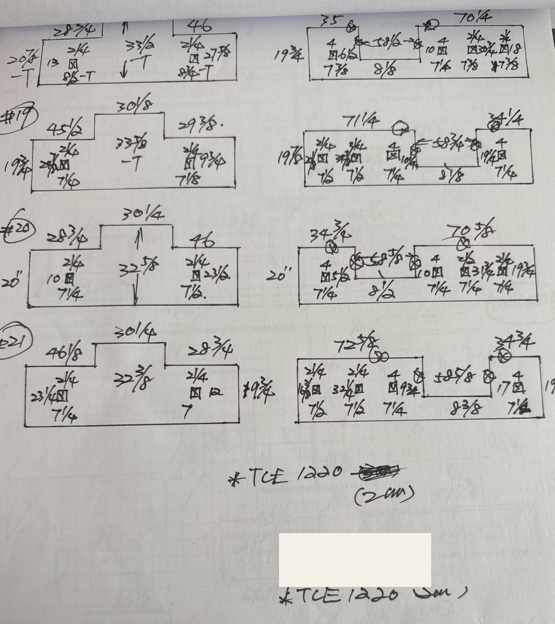
Three raised left panels retain separate row labels 19/20/21.
Center heights 33.875, 32.625, 32.375 and base heights 19.75, 20, 19.75 agree with retained readings.
Needs confirmation
Corresponding right-side notched wall panels and cropped upper row are not fully resolved.
Electrical openings have local callouts but need exact size/position confirmation.
TCE1220 2400 kg/m3 is a labeled family estimate.
The source images were visually reviewed; handwriting and field dimensions are not independently verified. Actual support positions and connection capacities are also unconfirmed.
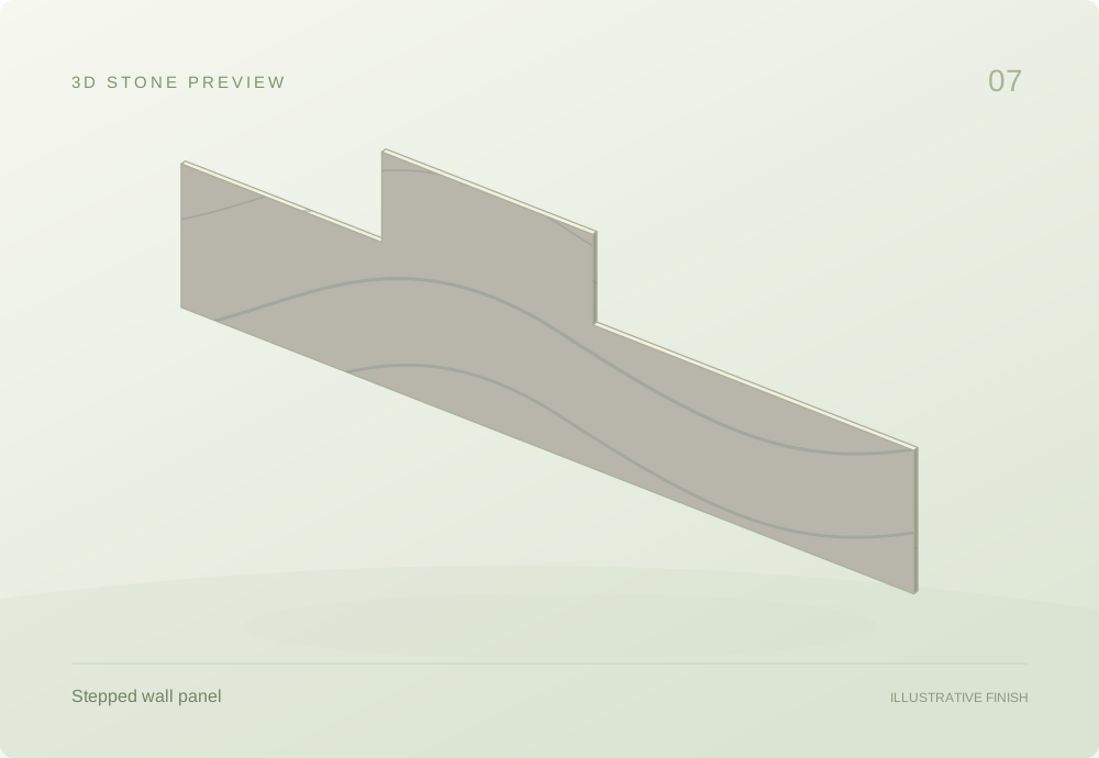
Assembly sketches join only faces supported by the drawing. Other pieces are grouped as sets. These are reconstructed schematics, not AutoCAD exports.
07.01 / SOLID STONE OUTLINE
Raised panel — drawing group 19
TCE1220
Related pieces share one view; spacing is schematic. Quantities remain in the table.
Gross estimates per piece · dimensions in inches; thickness in mm
Component
Qty
Size / thickness
Gross area m²
Est. mass kg
Est. weight N
Second row raised-center panelproject-7 · TCE1220
1
105 × 33.87520 mm thick
1.61
77.4
759
Thickness and density used in this table
Second row raised-center panel: 20 mm drawing reading; 2400 kg/m³ (Assumed study value).
Per-piece gross estimates. Sink and fixture openings are not deducted. Blank results need missing inputs; support examples may use separate, labeled assumptions.
The table records the gross outside outline, with quantities and per-component calculations.
Measurements & calculation steps
Second row raised-center panel
left shoulder: 45.5 in · center width: 30.125 in · right shoulder: 29.375 in · base depth: 19.75 in · overall depth: 33.875 in · overall length: 105 in · left Opening Horizontal Callout Reading: 29.875 in · right Opening Horizontal Callout: 9.75 in · left Opening Bottom Offset: 7.25 in · right Opening Bottom Offset: 7.125 in
A = 2,499.266 in² (rectangle addition) × 0.0254² = 1.61 m²
V = A × 0.02 = 0.0322 m³
ρ = 2,400 kg/m³ · Assumed study value
m = ρV ≈ 77.4 kg
Fg = mg ≈ 759 N
Gross external profile only; small outlet/fitting openings are not deducted.
outlet: width Reading: 2.25 in. Template and placement must be confirmed; not deducted from the gross outline.
07.02 / SOLID STONE OUTLINE
Raised panel — drawing group 20
TCE1220
Related pieces share one view; spacing is schematic. Quantities remain in the table.
Gross estimates per piece · dimensions in inches; thickness in mm
Component
Qty
Size / thickness
Gross area m²
Est. mass kg
Est. weight N
Third row raised-center panelproject-7 · TCE1220
1
105 × 32.62520 mm thick
1.60
76.9
754
Thickness and density used in this table
Third row raised-center panel: 20 mm drawing reading; 2400 kg/m³ (Assumed study value).
Per-piece gross estimates. Sink and fixture openings are not deducted. Blank results need missing inputs; support examples may use separate, labeled assumptions.
The table records the gross outside outline, with quantities and per-component calculations.
Measurements & calculation steps
Third row raised-center panel
left shoulder: 28.75 in · center width: 30.25 in · right shoulder: 46 in · base depth: 20 in · overall depth: 32.625 in · overall length: 105 in · left Opening Horizontal Callout: 10 in · right Opening Horizontal Callout: 23.5 in · left Opening Bottom Offset: 7.25 in · right Opening Bottom Offset: 7.5 in
A = 2,481.906 in² (rectangle addition) × 0.0254² = 1.60 m²
V = A × 0.02 = 0.0320 m³
ρ = 2,400 kg/m³ · Assumed study value
m = ρV ≈ 76.9 kg
Fg = mg ≈ 754 N
Gross external profile only; small outlet/fitting openings are not deducted.
outlet: width Reading: 2.25 in. Template and placement must be confirmed; not deducted from the gross outline.
07.03 / SOLID STONE OUTLINE
Raised panel — drawing group 21
TCE1220
Related pieces share one view; spacing is schematic. Quantities remain in the table.
Gross estimates per piece · dimensions in inches; thickness in mm
Component
Qty
Size / thickness
Gross area m²
Est. mass kg
Est. weight N
Fourth row raised-center panelproject-7 · TCE1220
1
105.125 × 32.37520 mm thick
1.59
76.1
747
Thickness and density used in this table
Fourth row raised-center panel: 20 mm drawing reading; 2400 kg/m³ (Assumed study value).
Per-piece gross estimates. Sink and fixture openings are not deducted. Blank results need missing inputs; support examples may use separate, labeled assumptions.
The table records the gross outside outline, with quantities and per-component calculations.
Measurements & calculation steps
Fourth row raised-center panel
left shoulder: 46.125 in · center width: 30.25 in · right shoulder: 28.75 in · base depth: 19.75 in · overall depth: 32.375 in · overall length: 105.125 in · left Opening Horizontal Callout: 23.25 in · right Opening Horizontal Callout: 12 in · left Opening Bottom Offset: 7.25 in · right Opening Bottom Offset: 7 in
A = 2,458.125 in² (rectangle addition) × 0.0254² = 1.59 m²
V = A × 0.02 = 0.0317 m³
ρ = 2,400 kg/m³ · Assumed study value
m = ρV ≈ 76.1 kg
Fg = mg ≈ 747 N
Gross external profile only; small outlet/fitting openings are not deducted.
outlet: width Reading: 2.25 in. Template and placement must be confirmed; not deducted from the gross outline.
WHY THE CALCULATIONS MATTER
Understand the material before planning the job.
Area and thickness determine stone volume. Density turns that into an estimated mass, and gravity gives its weight. These quantities support planning and discussion with the family business; supports, handling and installation need fabricator or qualified professional review.
Area → volume
A = L × D, or add rectangle areas
V = A × t
1 in = 0.0254 m
Table results are per component; quantity is shown separately. Sink and fitting templates remain notes until confirmed. Grouping does not combine different rooms or alternative sheet versions into one slab.
Volume → mass → weight
m = ρV
Fg = mg
g = 9.81 m/s²
Mass uses kilograms and weight uses newtons. A blank result means thickness or density is unconfirmed. Density assumptions and provisional readings remain identified in the calculation notes.
Original drawing references & material evidence
Original paper excerpts are preserved as references. Their appliance symbols and construction marks are not extra stone entries. Customer fields are removed.
project-7 · source reference
TCE1220
Study assumption: 2,400 kg/m³. A 2018 TCE Stone Oceania SDS lists a family range of 2,188–2,405 kg/m³. Regional formulation and applicability to this Canadian product code are unconfirmed.